🚀 Power your ESP32 projects like a pro — never miss a beat!
The FREENOVE Breakout Board is a precision-engineered terminal block shield designed exclusively for Freenove ESP32 and ESP32-S3 WROVER WROOM modules. It features multiple 5V and 3.3V power outputs capable of delivering up to 3A, an independent GPIO status LED for real-time signal monitoring, and a full pin header with 2.54mm pitch for seamless connectivity. Lightweight and compact, it optimizes your embedded development with reliable power and intuitive status feedback.
Brand | FREENOVE |
Item model number | FNK0091 |
Operating System | Embedded |
Item Weight | 2.82 ounces |
Package Dimensions | 4.92 x 3.27 x 1.06 inches |
Color | for ESP32 / ESP32-S3 |
Processor Brand | Freenove |
Computer Memory Type | SRAM |
Voltage | 5 Volts (DC) |
Manufacturer | Freenove |
ASIN | B0CD2512JV |
Country of Origin | China |
Date First Available | July 28, 2023 |
R**.
Best Proto Dev Board
These development boards are great. The screw terminations work well plus it has pins for connecting sockets.
M**A
great little easy way to use modules/mpus that are too wide for standard protoboard
Only tried with a couple of the ESP modules, some of which don't fit standard protoboard. Works great for those.I 'think' I really like the little state LEDs on each pin. Makes a really quick indicator of Vcc, 3.3 pins to verify orientation. I've not had issue with those LED indicators causing input pins to have an incorrect state.. it does include buffers between the pin and the LED/resistor, so maybe I am wrong. I do like the LEDs fwiw
P**K
Helpful for developers!
This board is a great time-saver for setting up and testing circuits with the ESP32. Definitely worth the price in time-saved, and frustrations saved.
Z**Y
External Power Needed for the middle red 5V pin column
This product is excellent for a PERMANENT setup for an ESP32 or ESP32 S3 board. I say permanent because external power is needed for the Red Line of pins, the 5V column. Any of the Ground Pins Column can be used in USB mode however. The 3.3V next to the Power Input can be used in USB mode, however there are only 8 pins for this usage.Pros:Each pin slot has a Female Hole for Male Pins for screwing it down to connect. Each pin has Male Connectors for Signal, 5V and Ground. There is also a set of 8 (Eight) male pins for both 3.3V and Ground.Cons:The column of Red Pins (5V) is only usable with an outside power source, 7-12V.
M**T
Amazing! Only works with this particular esp32
This thing is like the Lamborghini of break out boards. It has lights, multiple ways to connect to the esp as well as power. Easy to use, everything is labeled very well.It is only compatible with this esp32. There are many variations, so be sure to double check (ex-30vs38 pin, wroom vs wrover, etc).
P**R
Very Nice with ESP32-S3-DevKitC-1
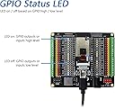
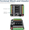
This breakout board is a real joy to use. It provides an LED indicator on nearly every pin, and accepts an external power source. Those LEDs are handy when troubleshooting, and they saved me time identifying connection mistakes quickly.Keep in mind, the screws on those terminals are tiny, but the supplied screwdriver is adequate. Once paired with my ESP32-S3-DevKitC-1, the assembly still fits in the box supplied with the product, which is kind of a bonus.This product may not work with every ESP32 variant, so pay close attention to the pinouts of your development board and compare with those found on this breakout board.At first glance, I wasn't sure this would work with my ESP32-S3-DevKitC-1, but it works great. The breakout board has 40-pins, but the (DevKitC) ESP32-S3-WROOM-1 breakout has 44-pins. The 40-pin socket simply plugs in to the middle 40 pins of the DevKitC, with one pin unconnected at each end. This is not a problem, since those pins are redundant 3V3 and GND pins.Just for fun, enjoy this quick sample code to see all those LEDs in action:#include <Arduino.h>const int gpioPins[] = { 4, 5, 6, 7, 15, 16, 17, 18, 8, 3, 46, 9, 10, 11, 12, 13, 14, 2, 42, 41, 40, 39, 38, 37, 36, 35, 0, 45, 48, 47, 21, 20, 19};const int numPins = sizeof(gpioPins) / sizeof(gpioPins[0]);void setup() {for (int i = 0; i < numPins; i++) {pinMode(gpioPins[i], OUTPUT);}}void loop() {for (int i = 0; i < numPins; i++) {digitalWrite(gpioPins[i], !digitalRead(gpioPins[i]));delay(100);}}update: I'm taking a few stars off. The 5V signal pin on the breakout isn't connected with the DevKit 5V pin.The product description clearly states the abundant (red) 5V0 pins on the breakout are only powered by the external power supply. But the ESP32-S3-DevKitC has a dedicated 5V pin from the 5V+ supplied by either USB port. FYI, the USB port powers the DevKit when no external supply is used. This pin is broken out in the lower-left corner to a blue LED. But, sadly, it is NOT connected to its adjacent (yellow) signal pin. Instead, the pin is tied to all the other (red) 5V pins powered by the external supply through the buck convertor. As far as I can tell, this is the ONLY (yellow) signal pin on the breakout not connected with the corresponding pin on the DevKit. The whole point of the breakout is to make connection with and troubleshooting of the smaller DevKit easier. I presume the designer of this breakout felt users may try to power external devices from the yellow 5V signal pin, and felt it necessary to block them from doing so.
G**O
Great for prototyping!
This board makes prototyping the ESP32 so much easier. Just be sure to buy the actual ESP32 from the same brand.
S**H
Awesome breakout board
This is an awesome breakout board, it made working with a pi pico much easier.Great designed and well constructed, it has firm connections but still is easy to remove. I find it is worth the price, I may buy a few more.
Trustpilot
2 months ago
1 month ago