⚙️ Unleash the Power of Precision Control!
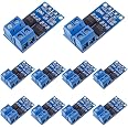
The EPLZONMOS Switch Drive Module is a high-performance electronic switch control board designed for DC motors and high-power equipment. With a voltage range of DC 5V-36V and a maximum current of 30A, this module supports PWM signal control for precise adjustments in speed and brightness. Its robust design ensures reliable operation in extreme temperatures, making it a versatile choice for various applications.
| Manufacturer | EPLZON |
| Part number | EP-SWITCH-15A |
| Item Weight | 0.28 g |
| Product Dimensions | 14.83 x 10.59 x 1.91 cm; 0.28 Grams |
| Item model number | EP-SWITCH-15A |
| Wattage | 400 watts |
| Item Package Quantity | 1 |
| Switch style | MOSFET |
| Batteries included? | No |
| Batteries Required? | No |
C**O
works like a charm
Put these to use in a large LED lighting system ... they handle the drive current with no problem. Much easier than building my own boards.
C**N
I'll definitely order more of these
I used two of these to drive four 60 watt Peltier thermoelectric coolers (TEC) from an ESP32. They work nicely at all duty cycles from the PWM controller.I didn't notice any heat from the MOSFETs with this small loadThe LED on the board is a nice indicator of the duty cycle
W**7
Excellent way to drive low DC voltage devices at high or low from a MCU like an Arduino
MOSFETs are great devices for switching low voltage devices from microcontroller units like Arduinos. They are solid state so they can be switched at high speed unlike relays and so can be used for pulse-width modulated (PWM) loads. Their internal resistance is low so they can switch high currents without getting (too) hot and there is minimal voltage drop to the load.These board modules from EPLZON use two MOSFETs in parallel so the effective current capacity is doubled and the internal resistance is effectively halved. The MOSFETs used are the D4184. These are N-Channel MOSFETs which have a typical internal source-drain resistance of typically 8.5mΩ with 4.5V applied to the gate (as expected from an Arduino). Thus, the effective internal resistance with two MOSFETs in parallel will be 4.25mΩ which gives the device the ability to supply such high currents without the need for a heatsink. Compare this with another popular module which uses a single IRL520 MOSFET with an internal resistance of 270mΩ which is over 60x worse and will need a heatsink with currents above 1A.The 10 modules were supplied as two strips of five, still joined together. They were easy to snap apart. The quality of the boards looked good although the terminal blocks’ mounting positions looked very erratic. One issue I had with these boards was that they were not easy to mount. There were two small holes on the front edge but these were close to the input connector pads and so metallic pillars could not be used. There was no support on the far edge. It looks like glue may be the best way to mount this board onto a surface. Although terminal blocks are provided to connect the power supply and the load, no connectors are provided for the control input signal. I didn’t find this to be much of a problem as it depends on how I wanted to use the module (e.g. standalone or mount on another PCB). It was easy to solder on a 4pin 2.54mm header.The module circuit was very basic – just the two MOSFET devices and a couple of resistors to condition the input line. There was also an LED attached to the input line to indicate when the MOSFET was switched on. Note that these N-channel devices drive the load by effectively shorting its -ve terminal to ground when a positive signal is applied to the control input. The +ve load terminal is continually connected to the positive power supply line (which is normally a different PSU to that powering the MCU). The OAD4184 datasheet indicates that the device can be switched on with a control input voltage above typically 2.2V, so it can be controlled with a 3.3V based MCU (e.g. Raspberry Pi, ESP8266, ESP32, etc.). This is not the case with the competitive IRL520 MOSFET boards which need a higher control input voltage. Note that if the load is capacitive or inductive, a fly-back diode should be wired in parallel with the load – to prevent potential damage from back EMF to the MOSFET.Just because these boards can handle really high currents (although I’m not sure I would even feel safe in passing 30A through these little boards), doesn’t mean that they can’t be used for low current applications. In fact, most of my circuits only need a few amps at most and these boards work really well for them. The example shown in the image is to drive a 12V LED from an Arduino Nano as an alert indicator. This LED only needed 40mA at 12V to turn fully on and the MOSFET board worked well with only two wires needed to drive it from the Nano. A sketch was developed for the Nano to pulse the LED slowly on and off using PWM.In summary, I think these are very useful boards to drive low voltage DC loads at high or low currents from an MCU like an Arduino. They are cost effective and work well. My only issue was the difficulty in mounting the boards but a dab of glue should fix this. This product is a great improvement over competitive boards using the IRL520 MOSFET.
M**T
Failed closed within seconds, drastically overheats within seconds
It’s rated for 36V at 15A but it does not survive that, not even for two seconds. I tried two, both burned out and failed closed, driving my servo motor into the wall while heating up within milliseconds to untouchable temperatures. Will return. Definitely disappointed!
B**N
I have used these for a few ESP32-based projects already and all have worked well
I did some pretty through testing on these before opting to go for it. The y are mystery bin mosfets which lead me to slight hesitancy with projects which live in hard conditions or perform vital tasks but the majority of my small projects are just for small jobs with no really pressure involved. They have worked out great so far with small heaters, fans and lights where PWM functionality reigns supreme. So far, not one mosfet has failed. Worth noting: there is no lead on the control side of the boards and the combo comes as one big card which you need to snap apart so you will have a little bit of work to do; however, it’s worth it!
Trustpilot
4 days ago
2 weeks ago